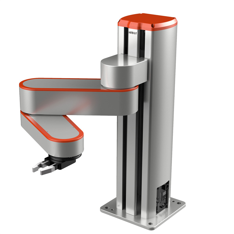
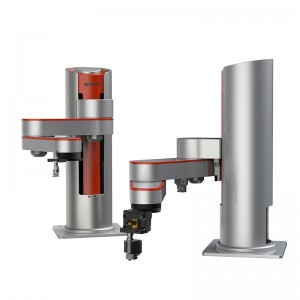
SCARA ROBOTIC ARMS – Z-Arm-2142E Collaborative Robotic Arm
Main Category
Industrial robot arm /Collaborative robot arm / Electric gripper/Intelligent actuator/Automation solutions
Application
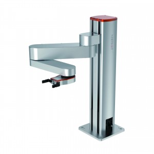
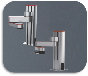
SCIC Z-Arm cobots are lightweight 4-axis collaborative robots with drive motor built inside, and no longer require reducers like other traditional scara, reducing the cost by 40%. SCIC Z-Arm cobots can realize functions including but no limited to 3D printing, material handling, welding, and laser engraving. It is capable of greatly improving the efficiency and flexibility of your work and production.
Features
High Precision
Repeatability
±0.03mm
Large Payload
3kg
Large Arm Span
JI axis 220mm
J2 axis 200mm
Competive Price
Industrial-level quality
Competitive price
Related Products
Specification Parameter
The SCIC Z-Arm 2142 is designed by SCIC Tech, it is lightweight collaborative robot, easy to program and use, support SDK. In addition, it is collision detection supported, namely, it would be automatic to stop when touching human, which is smart human-machine collaboration, the security is high.
|
Z-Arm 2142E Collaborative Robot arm |
Parameters |
|
1 axis arm length |
220mm |
|
1 axis rotation angle |
±90° |
|
2 axis arm length |
200mm |
|
2 axis rotation angle |
±164° |
|
Z axis stroke |
210 Height can be customized |
|
R axis rotation range |
±1080° |
|
Linear speed |
1220mm/s (payload 2kg) |
|
Repeatability |
±0.03mm |
|
Standard payload |
2kg |
|
Maximum payload |
3kg |
|
Degree of freedom |
4 |
|
Power supply |
220V/110V50-60HZ adapt to 24VDC peak power 500W |
|
Communication |
Ethernet |
|
Expandability |
Built-in integrated motion controller provides 24 I/O + under-arm expansion |
|
Z-axis can be customized in height |
0.11m, 0.21m, 0.31m, 0.41m, 0.51m |
|
Z-axis dragging teaching |
/ |
|
Electrical interface reserved |
Standard configuration: 24*23awg (unshielded) wires from the socket panel through the lower arm cover Optional: 2 φ4 vacuum tubes through the socket panel and flange |
|
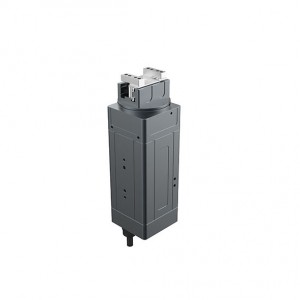
Compatible HITBOT electric grippers |
Z-EFG-8S/Z-EFG-12/Z-EFG-20/Z-EFG-20S/Z-EFG-30/Z-EFG-50, Fifth axis, 3D printting |
|
Breathing light |
/ |
|
Second arm range of motion |
Standard: ±164° Optional: 15-345deg |
|
Optional accessories |
/ |
|
Use environment |
Ambient temperature: 0-45°C Humidity: 20-80%RH (no frost) |
|
I/O port digital input (isolated) |
9+3+forearm extension (optional) |
|
I/O port digital output (isolated) |
9+3+forearm extension (optional) |
|
I/O port analog input (4-20mA) |
/ |
|
I/O port analog output (4-20mA) |
/ |
|
Robot arm height |
566mm |
|
Robot arm weight |
210mm stroke net weight 18kg |
|
Base size |
200mm*200mm*10mm |
|
Distance between base fixing holes |
160mm*160mm with four M8*20 screws |
|
Collision detection |
√ |
|
Drag teaching |
√ |
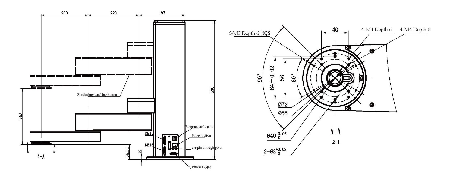
Motion Range M1 Version (Rotate Outwards)
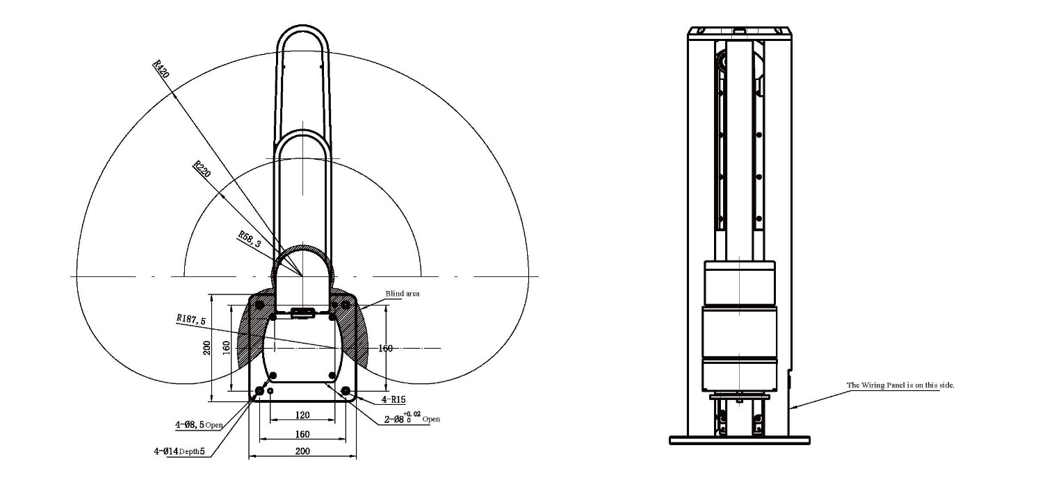
Interface Introduction
The Z-Arm 2442 robot arm interface is installed in 2 locations, the side of the robot arm base (defined as A) and the back of the end arm. The interface panel at A has a power switch interface (JI), 24V power supply interface DB2 (J2), output to user I/O port DB15 (J3), user input I/O port DB15 (J4) and IP address configuration buttons (K5). Ethernet port (J6), system input/output port (J7), and two 4-core straight-through wires sockets J8A and J9A.
Precautions
1. Payload inertia
The payload center of gravity and the recommended payload range with the Z axis movement inertia are shown in Figure 1.
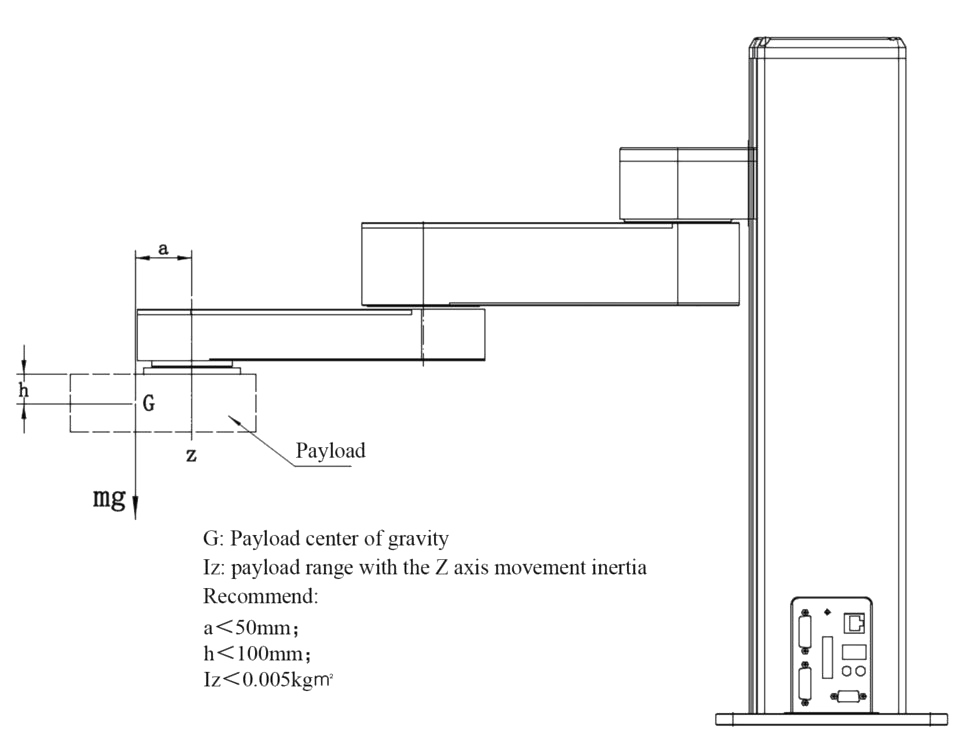
Figure1 XX32 series payload description
2. Collision force
Trigger force of horizontal joint collision protection: the force of XX42 series is 40N.
3. Z-axis external force
The external force of the Z axis shall not exceed 120N.
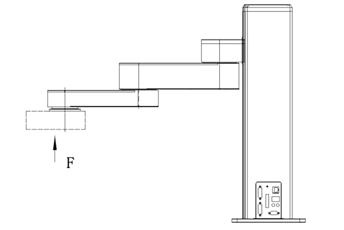
Figure 2
4. Notes for installation of customized Z axis, see Figure 3 for details.
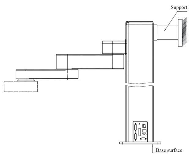
Figure 3
Warning Note:
(1) For customized Z-axis with a large stroke, The Z-axis rigidity decreases as the stroke increases. When the Z-axis stroke exceeds the recommended value, the user has the rigidity requirement, and the speed is >50% of the maximum speed, it is highly recommended to install a support behind the Z-axis to ensure that the rigidity of the robot arm meets the requirement at high speed.
The recommended value are as follows: Z-ArmXX42 series Z-axis stroke >600mm
(2) After the Z-axis stroke is increased, the verticality of Z-axis and the base will be greatly reduced. If strict verticality requirements for the Z-axis and the base reference are not applicable, please consult the technical personnel separately
5.Power cable hot-plugging forbidden. Reverse warning when the positive and negative poles of the power supply are disconnected.
6. Do not press down the horizontal arm when the power is off.
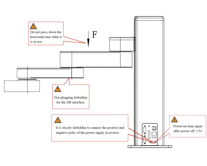
Figure 4
DB15 Connector Recommendation
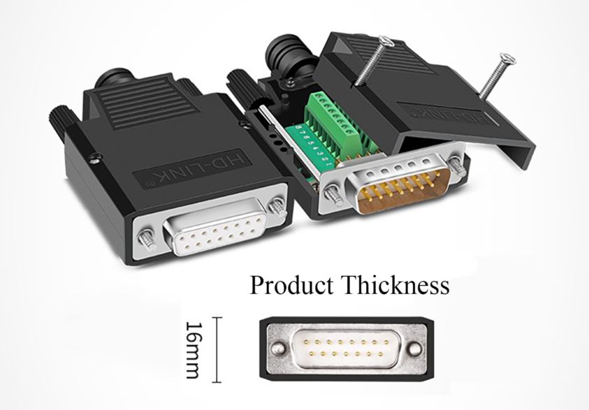
Figure 5
Recommended model: Gold-plated male with ABS shell YL-SCD-15M Gold-plated female with ABS shell YL-SCD-15F
Size Description: 55mm*43mm*16mm
(Refer to Figure 5)
Robot Arm Compatible Grippers Table
|
Robot Arm Model No. |
Compatible Grippers |
|
XX42 T1 |
Z-EFG-8S NK/Z-EFG-12 NK/Z-EFG-20 NM NMA/Z-EFG-20S/ Z-EFG-30NM NMA The 5th axis 3D printing |
|
XX42 T2 |
Z-EFG-50 ALL/Z-EFG-100 TXA |
Power Adapter Installation Size Diagram
XX42 configuration 24V 500W RSP-500-SPEC-CN power supply
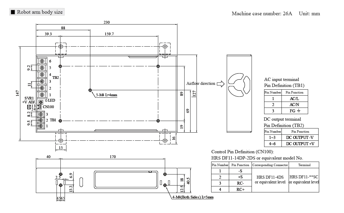
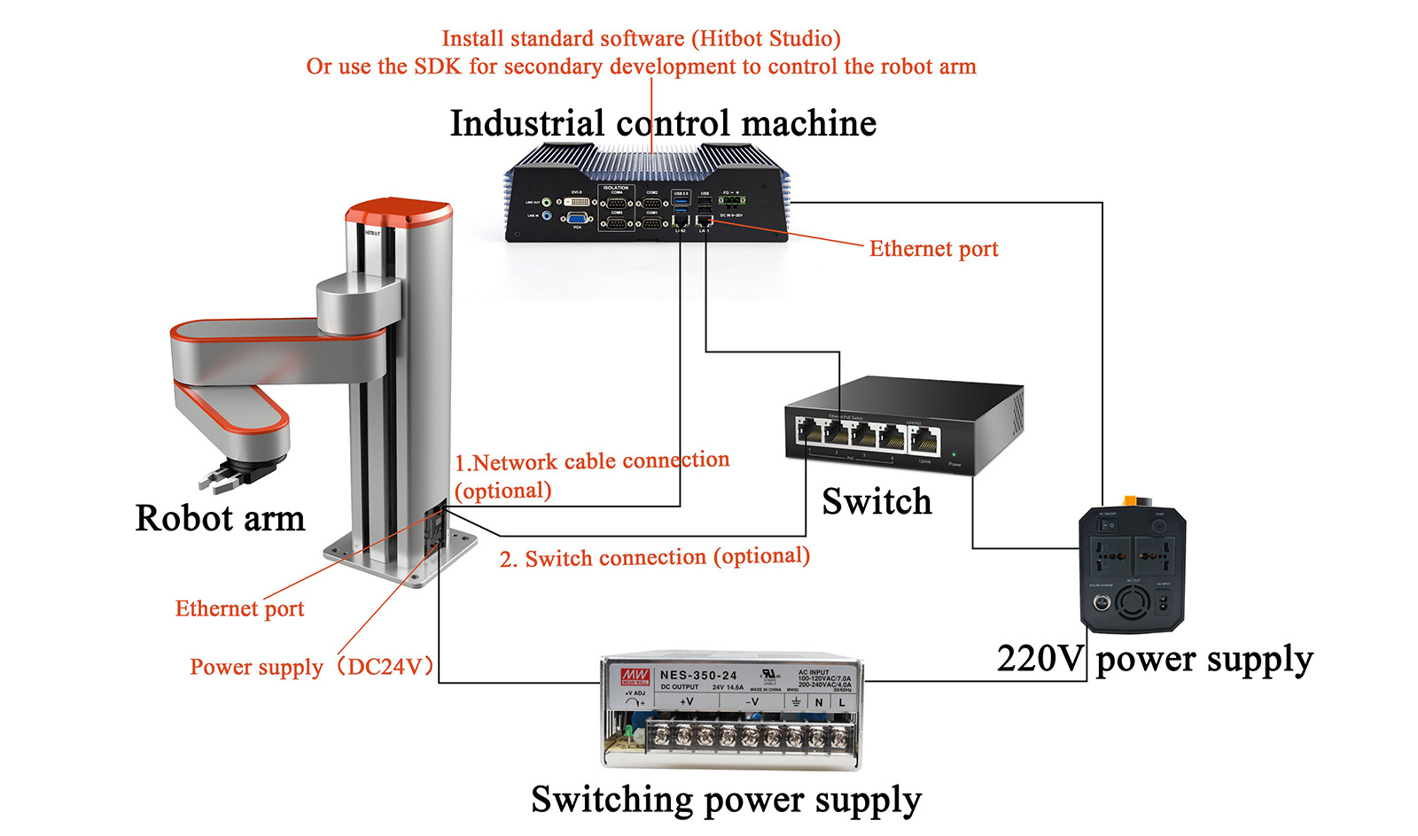
Diagram of The External Use Environment of The Robot Arm
Our Business
